

259/1A 3rd Floor, ADA Rd, Vinoba Nagar, Naini, Prayagraj, Uttar Pradesh 211010
05323557581, +919555433745 (9am - 8pm IST, Monday - Saturday)
Training | Development | Internship
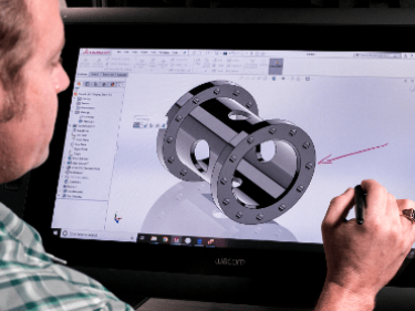
SolidWorks is an industry leading CAD system that allows users to create complex models and designs. The only prerequisite to learn SolidWorks is possessing the ability to translate views into 3-D and vice versa.
| Track | Week Days | Course Duration | Fast Track |
|---|---|---|---|
| Course Duration | 45 - 60 Days | 10 Weekends | 15 Days |
| Hours | 2 Hrs. Per Day | 3 Hrs. Per Day | 6+ Hrs. Per Day |
| Training Mode | Classroom/Online | Classroom/Online | Classroom/Online |

I've been going to Conax Infotech for 4 years now, and I can confidently say it is the best Solidworks training institute around. They have a great team of instructors that provide training for all levels, from beginners to expert.

If I had to recommend a place to study Solidworks, I would say definitely go with Conax Infotech. They offer the best Solidworks training and have a long history of success in helping students learn this important software.

I have been to many training institutes and have seen that Conax Infotech has the best Solidwork training institute in town. They teach you the basic concepts of Solidworks very well and help you get your feet wet with all of its tools.